|
|||||||||||||||||||||||||||
|
|||||||||||||||||||||||||||
|
|
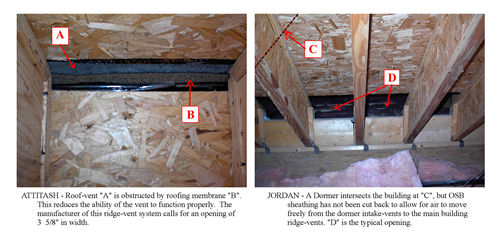
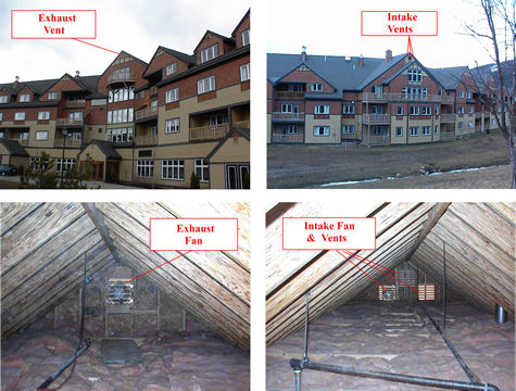
Ventilation ReportIntroductionIn this report we will take a close look at the attic ventilation systems of the four hotels and examine how they are contributing to ice damming. We performed ventilation assessments for each hotel and these were submitted with the original hotel reports. They are attached to this report as Attachments A through D. In this report we will cover the following topics: A General Discussion of Ventilation, A Detailed Inspection of an Attic Section, Ridge Vent Failure caused by Major Snow Loading, A Comparison of the Hotel Architect's (JSA) Ventilation Calculations to Ours, Ventilation Standards, Results of the Jordan Bowl Ventilation Experiment, Results of the Killington Ventilation Experiment, and Conclusions and Recommendations. A General Discussion of VentilationThe severity of the ventilation problem wasn't immediately apparent. First, it was reasonable to assume that the ASC Hotels were designed, engineered, and built to ventilate properly. Also, the initial inspection of the attics didn't reveal evidence of the moisture problems such as mildew, wood-rot, or condensation watermarks that are usually associated with poor ventilation. Soffit and ridge venting could be observed as installed. However, the more time we spent in the attics, the more trouble-signs we began noticing. For example, areas of ridge vent were noticed to be obstructed and even completely covered by roofing membrane or OSB. Also, the OSB panels used for roof sheathing were cut back in a very limited fashion where the dormers joined the building (see photos below). This is problematic because a large percentage of the intake vents are located within the dormers, and air must pass through this area to assist in ventilating the main attics.
From the empirical evidence furnished by analysis of collected temperature data and from the physical evidence observed in the field, it became apparent that a detailed inspection of the ventilation systems of all four hotels was necessary. These “Ventilation Assessments” were completed for all four hotels and submitted to ASC. A summary of the inlet and outlet roof vent problems is included in Attachment H. The complexities and inadequacies of the attic ventilation in the hotels are too great to elaborate on here, but we should touch on some of the most significant findings: General ventilation rules of thumb, such as “1 square-foot of ventilation for every 150 or every 300 square feet of attic area”, averaged over the entire hotel, cannot be assumed to deliver the desired ventilation in all attic areas of the hotel equally when there are additional complexities, such as firewall divisions, OSB divisions, loft units, etc. that make certain attic areas unique or isolated from others. Each integral attic area must have its own adequate ventilation. The Moisture Control Handook states this necessity as: Vents should be distributed ... to prevent zones of dead or stagnant air and
should not be blocked by roof assembly insulation or other obstructions.[4] Vent systems in place at each hotel were installed in a manner that didn't allow for the manufacturer's performance specs of the components to be fully realized. This is due to improper installation and/or obstructions to the components. This applies to all four hotels, for both intake and exhaust ventilation components. BOCA National Building Code minimum ventilation requirements for attics are not achieved in any of the hotels. We reviewed this standard across BOCA Code for 1993, 1996, 1998 Supplement, and 2000. Each hotel is under its own building code jurisdiction and corresponding local requirements may be other than BOCA National Building Code. Also, the code that was in force at the time of construction may be different than that which is in place now. However, BOCA is generally consistent over these years and serves as a very useful standard that most professionals use as a guide for designing attic ventilation. This and other standards are reviewed in the Standards section of this report. The “attic area” that is typically used for calculating the “1:150” and “1:300” rules (see #1 above) consists of only the area of the attic floor. We had observed that at the ASC Hotels loft walls and cathedral ceilings also provided surfaces where warm air was exfiltrating into the attics (see “Diagram 3”, page 3). We asked BOCA for a ruling (see Attachment K) on whether these walls should also be included in sizing attic ventilation and received this reply: The area of these walls, which separate the occupied and uninhabited spaces, must be included in the calculation, along with the ceiling areas, to determine the net free ventilating area. [9] (see Attachment L) This is very significant because these walls and ceilings add up to (conservatively) 20% or more of additional surface area in some attics, and original attic ventilation calculations and subsequent design did not consider them. The JSA Comparison section (see Attachment G) of this report details this in more depth. Prudence would dictate that in buildings as complicated as these hotels, ventilation should be over designed or, if the standard ventilation minimums are to be used, that they be verified to be effective by testing in the field. This would have revealed the kinds of problems that we later discovered, such as: blocked ridge vents, snow loading diminishing the effectiveness of ridge vents, attic warming from solar-gain, unbalanced inlet and outlet vents, blockage of inlet vents in dormers from reaching main attics, fiberglass batts blocking vents, framing members blocking vents, unaccounted for duct leakage, overly long soffit vent chute runs, and bay dormers completely isolated from venting to the main attics. A Detailed Inspection of an Attic Section
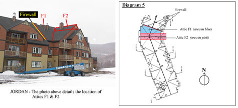
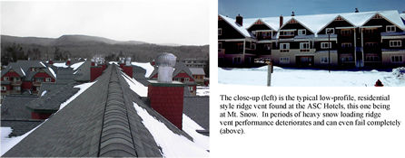
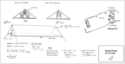
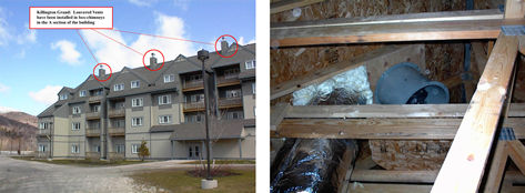
Let's examine one of the above findings as it applies to an attic area at one of the hotels. In our first finding, (“#1” above) we state that given the complexities of these hotel attics, the 1:150 or 1:300 rule applied over the entire hotel would not necessarily serve all attics equally. Attic “F2” at Jordan Bowl is located above Room 313 and runs perpendicular to the axis of the building. Next to it on the north side is Attic “F1”. Attic F1 is isolated from all other attics by a firewall on its north side and by OSB, which forms the cathedral roof sheathing of neighboring Attic F2 (see photo and Diagram 5 above). Whereas Attic F2 runs east-west and the hotel axis runs north-south, there are no soffit vents from the outside of the building that reach into this attic. An inspection revealed that the ridge vent in this attic is completely blocked. Consequently, there is no ventilation of this attic regardless of the overall hotel ventilation. Attic F1 is within a “knuckle” area where the building makes a shift in direction, thus one side (the east) has a very short wall area (4 ft.) for intake vent. This is entirely obstructed by a 2" x 8" framing member. On the longer side, only 9 ft of the available 14 ft has soffit-venting that makes it into this attic. The ridge vent is also obstructed from full operation by roofing membrane and OSB roof sheathing. If the 1:300 ventilation rule is applied to this attic, with its 768 square feet (sq. ft.) of floor area, there should be 2.56 sq. ft. of net free ventilation area (768/300), which should be balanced between intake and exhaust (1.28 sq. ft. intake/1.28 sq. ft. exhaust). Our inspection determined that there is only 0.6 sq. ft. of operational soffit vent and 0.5 sq.ft. of operational ridge vent. This means that this attic has less than 40 % of the required ventilation. A Major Ventilation Concern: Ridge Vent FailureAs our repair work was reaching completion, and in fact we had only one visit left to make to Mt. Snow, a very interesting event occurred. We had been tracking and analyzing temperature data throughout the project's duration and had developed a clear understanding of the conditions and the typical performance of the attics in the four buildings. As we reviewed temperature readings in preparation for reporting on project progress we noticed an incredibly dramatic increase in attic temperatures at the attics of all four hotels beginning February 13 at Mt Snow and continuing through February 18 at Jordan Bowl. It was difficult to identify a cause for this from the ISSAC data. Why would attic temperatures suddenly increase after so much repair work had been completed? We knew this couldn't be related to hatches being open into the attics (something we had on occasion been able to deduce from the ISACC readings), because it applied to all the attics at all of the hotels. Furthermore, our experience from previous air-sealing projects, observations in the attics, and our infrared scanning diagnostics of the repair work, made it clear that this was not a problem associated with the air barriers Collecting and analyzing data by remote means provides information only about temperature readings at the collection site. There is no information about other climatic factors. What we did see around us, though, were houses covered with up to two feet of snow. The snows this year had come late and now seemed to be making up for lost time. Though there had obviously been snow at the ski areas prior to this, accumulation was moderate. What had happened was this - the ridge vents had been rendered inoperable by the large amount of snow cover. Ridge vents can function under some snow loading and are cleared by winds at other times, however, at certain times they are shut down completely (see photo below).
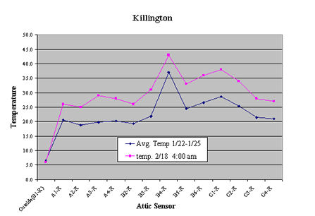
The result of ridge vent failure is disastrous from an ice damming standpoint. Warm air that accumulates in the attics cannot escape and starts to melt the snow on the roof. It isn't long before significant snow melting leads to the colossal ice dams and icicles that are all too familiar on the ASC Hotel roofs. The graph below (Graph B) shows the “spike” in temperature that was evident when the ridge-vents failed. Graph B is for Killington, but the same phenomenon could be seen at the other hotels. The red line on the graph is for an hourly reading at the time of heavy snow loading (2/18) where the outside temperature reading matches the average temperature reading for the “control period” of 1/22 through 1/25 (after repair work/no significant snow on the roof). The graph clearly shows the contrast between the two periods. (Also evident in the graph is the tremendous heat loss that continues to emanate from the duct-vent into Attic B4). Graph B
From an air-sealing standpoint this presented a real dilemma. While we could see that our repairs to the air barrier were moving the attics very close to exiting the Icing Envelope, there would remain times when the improved attics would still be completely overwhelmed by snow-covered ridge vents. Attempting to correct this deficiency through further improvements to the air barrier and/or increases to the R-Value of the thermal envelope would not be at all cost-effective. The solution is to provide adequate ventilation that is designed to work in times of deep snow. A Comparison of the Hotel Architect's (JSA) Ventilation Calculations to OursThe ISAAC data and our assessment of the completed air sealing indicated that ventilation was the issue that had to be addressed next. At the same time, the Architect's (JSA) report showed that the ventilation should be up to the standards we needed. In order for everyone involved to understand this discrepancy, we did as direct a comparison as possible of their and our assessments (4-6-00). Each of the line items of the ventilation studies was compared with discussion of the causes of the differences. The HCF net free area, depending on snow cover considerations, varied from as little as 14% to as much as 54% of the JSA Study results. (This comparison is detailed in Attachment G.) The net free areas measured by HCF for each hotel that supports this comparison is detailed in our “Roof Vent Diagnostic Report” for each hotel (see Attachments A through D). In Table A of each hotel's report, the net free area is analyzed on an attic-by-attic basis. In the majority of the attics, the percent of functional ventilation area is a small fraction of that required. On May 21, H. C. Fennell, Inc. updated its comparison of the JSA and HCF attic ventilation assessments. The primary change was increasing the attic surface area. This new number includes the walls of the lofts facing the attics and the surface area of ductwork carrying conditioned air through the attics. (“Heating and ventilating ducts that pass through the attic should be well sealed and insulated and the heat they add to the attic should be considered when sizing the ventilation system.” [3]) The change is based on a code ruling by BOCA International (see Attachment G) which was solicited earlier but was received after the original ventilation report was submitted to ASC. In summary, both comparisons show that the original JSA calculations failed to take as-built and site-specific environmental conditions into account. In addition, exception rules allowing the use of the 1:300 rule were applied to all cases of the available calculated areas rather than just to the relevant areas. Attic Ventilation StandardsMany building code issues are not enforced at the state level, but may be enforced by the local code officials. This leaves the responsibility to make the building perform successfully to the design and construction professionals. Most local code authorities, architects, and contractors rely on the BOCA code as a guideline for good design and construction practices, even in the absence of enforcement. Applicable Standards and Commentary
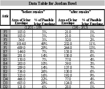
The BOCA Building Code for attic ventilation is concerned with controlling moisture. Coincidentally, “the amount of ventilation needed to prevent condensation is usually enough to minimize icing.”[5] The intent of the net free vent area for attic ventilation is to produce an adequate air flow and exchange rate to remove moisture from the roofs or attics. However, as the complexity and size of the roofs and attics increase, air exchange rates are likely to drop. Therefore, in order to overcome the lower air exchange rates, additional natural ventilation or mechanical ventilation is needed. For example: Venting cathedral ceilings should follow the 1:150 ventilation standards (not the 1:300). “If cathedral ceiling assemblies are ventilated (as is Roof 2), a minimum of 1 square foot of vent area should be provided for every 150 square feet of insulated ceiling area.”[5] Ventilating air traveling up through long vent chutes in cathedral ceilings will take on heat and moisture as it moves upward. “As cold, dry, outdoor air moves from the eaves to the ridge of a cold (ventilated) attic less roof, it picks up moisture and heat. By the time it has traveled about 6m (20ft) in the narrow spaces above the insulation, it is no longer very effective at keeping the surface of the roof cold.” [5] This is the case at ASC. Most of the ventilation starts in lower roofs or travels through restricted passages from dormers; therefore, the air is already pre-heated by the time it reaches the large main attics. For this reason, the majority of the ASC attics do not meet the standard for using the 1:300 exception and require a minimum of 1 square foot of vent area for every 150 square feet of attic surface. Results of the Ventilation Experiment at Jordan Bowl in Attic F2 (above Room 313) OverviewWe chose this site for our first ventilation experiment because it is one of the warmest of all the hotels. In fact, when we began this project it was the warmest (see Table 4 and Table 5 below). By the time air-sealing repairs were completed it had improved significantly and moved to second worse on the list. The logic here is that if we could finish moving this attic out of the Icing Envelope with ventilation, then we would be able to move all of the other less problematic attics out of the Icing Envelope as well. This attic is above Room 313 in the Jordan Grand Hotel. Table 4:
The repair work that has been completed since the baseline period was successful in improving the air barrier between the attics and the heated hotel space, and the difference between exterior and attic temperatures, as a result, has been significantly reduced. We have reported on this previously and present it here again in Table 5, which summarizes the results: Table 5:
We concluded from this information that further repair work on the air barrier would not be cost-effective and that what is necessary from here is to improve attic ventilation. This was decided by the combination of infrared assessment of the air barrier and inspection of the ventilation that was in place in this attic (see “A Detailed Inspection of an Attic Section”). It was this deficiency in ventilation that we endeavored to improve with our experimental installation at Jordan Bowl. The Ventilation ExperimentBelow is a sketch that was used in the process of designing improved ventilation for the F2 Attic:
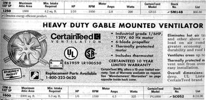
Two fans of the type pictured below were installed in an intake-exhaust configuration:
We designed the attic ventilation system and the plan was implemented with the assistance of Dan Noble's crew. It should be noted that the fans weren't intended yet to be permanently installed and that at some later date they should be: a) fitted with a cowl to further improve performance, and b) brought under the control of the ISACC so that they will operate thermostatically, only at times of need.
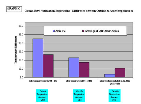
Quantitative AssessmentThe attached graph (Graph C) shows that attic F2, which originally was the warmest hotel attic, as result of the repair work and power ventilation, has become one of the coolest:
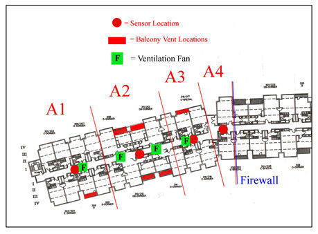
Discussion of Graph CIn this histogram, three time-periods are examined: 1) before repairs to the attic air barrier took place, 2) after the repair work was completed, and 3) after two ventilation fans were installed in the F2 Attic. The bars show the difference between attic temperatures and the outside temperature. The average temperature of “All Other Attics” at Jordan are lumped together in the maroon bar on the right. The blue bar is for Attic F2, the site of our ventilation experiment. The cut-off point for the data is set at 8 degrees (F). This is because the “Icing Envelope” formula is based on a difference between exterior temperature (22 F) and attic temperature (30 F) of 8 degrees or less. After extensive repair work and the installation of power ventilation, the F2 attic is very close to exiting the icing envelope. With slight modification to the fans installed in the F2 Attic (as it is converted to a permanent installation) and with the improved venting of the adjacent Attic F1 (now the warmest remaining attic at Jordan, which continues to contribute to warming F2), Attic F2 will no longer be problematic. The attic that was the warmest attic at the hotel will no longer contribute significantly to ice damming. Given that this was the second warmest attic in all four hotels, the same procedures that have worked here should clearly be successful when applied to less troublesome attics. Results of the Ventilation Installation at the Killington GrandAn entire attic section was chosen for a second ventilation experiment. We also chose an area that was contiguous, meaning there weren't any significant changes in attic configuration or the existence of obstructions between attics (as there are in other ASC attic areas). The floor area for these attics totaled 11,145 feet and the volume of air in this area necessitated the installation of five large fans, each capable of exchanging a minimum of 3,900 cubic feet per minute. To supply these fans with the necessary intake required for effective operation, the intake ventilation area needed to be increased significantly. Five fans were installed, but only four had outlet vent cutouts. The fifth fan, located in the Attic A4 “knuckle area”, would have required building a different outlet than that used by the other four fans and the decision was made by ASC not to pursue this at this time. Further, it was also decided to hold off on installing increased intake ventilation to supply the attics. This left the experiment with 20% less exhaust and 60% less intake area than was planned for successful ventilation of the attic. Nonetheless, the experiment went forward resulting in significant findings (see photos below).
We ran the fans for two weeks, gathering temperature readings for a period before, and then during the improved ventilation. We also involved a professional data monitoring consultant in this work to assist in statistical methodology and to corroborate our findings independently [11]. He set up his own monitoring equipment at Killington to measure the effect of the power ventilation experiment. As a result of the limitations to this experiment (in the time-honored tradition of experiments!) we didn't find exactly what we were looking for (i.e. significantly cooler attics completely out of the Icing Envelope), but both monitoring experiments did find significant results nonetheless. We had hoped to see a dramatic improvement in the cooling of all of the attics in this section, but this didn't happen. We were aware that the specified amount of net free area of inlet for the fans had not been provided, but hoped the attics could still be cooled by power ventilation. Instead, only the attic that already had, coincidentally, almost twice the intake (in the form of balcony vents) as the other nearby attic zones, ended up showing significant improvement. This attic, in fact, was moved out of the Icing Envelope with the increased ventilation. What we learned from this experiment is that adequate and evenly distributed intake is essential for power ventilation to work effectively in this type of large attic (see Diagram 6 below). Diagram 6
The diagram above illustrates very clearly why Attic A2 has been successfully corrected with the introduction of power ventilation. Additional inlet vent area was not provided for this experiment, but the concentration of balcony vents that coincidentally were already in place in the A2 Attic area were enough inlet to affect the desired change in this area. None of the other attics made it successfully out of the Icing Envelope with the existing undersized and poorly distributed inlet vents, demonstrating that balanced inlet and outlet net free areas (not averaged areas) are necessary for successful cooling of the attics. ConclusionsOur research analyzing the roof and attic ventilation at the four ASC hotels has shown that the existing ventilation in the buildings is inadequate. The “Attic Ventilation Assessments” (included in Attachments A - D) as well as the study we did comparing the existing ventilation systems to the required ventilation (see “JSA Comparison for Jordan” - Attachment M) details these findings. In specific attics, ventilation may be close to meeting the requirements, but in others it is virtually non-existent. Our test of two attics has shown that the attics can be moved out of the Icing Envelopes by adding ventilation employing relatively inconspicuous methods. One of the worst attics in the four hotels was able to reach this goal with two low-maintenance ventilation fans that could be automatically controlled and monitored with the existing ISAAC unit. The data from the tests of Attic F2 shows that improving the ventilation of all of the attics by the same amount that Attic F2 was improved, will move them all out of the Icing Envelope. Some attics may be able to be retrofitted to ventilate adequately with natural (passive) systems, but many of them will require mechanical ventilation because convenient locations for increased inlet or outlet areas are extremely limited, and because many of the inlet air paths are long and restricted. This study also shows that some interior work will be required to open ventilation paths between isolated attic areas (such as where overlaying dormers serve as inlets for the main attics) and to provide evenly distributed ventilation. Recommendations
Related Information
| |||||||||||||||||||||||||

|
|||||||||||||||||||||||||||