|
|||||||||||||||||||||||
|
|||||||||||||||||||||||
|
|
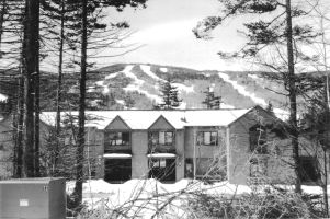
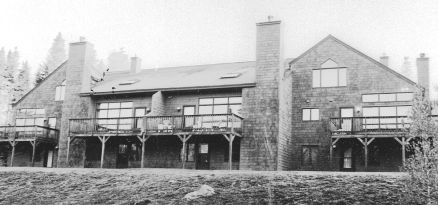
Case StudyRoof Ice Dam Remediation for Northeast Ski-AreaCondominiumsPart Iby Henri C. Fennell IntroductionThe owners of these condominiums had experienced a number of "snow country" problems. At the head of their list was ice dams. While the buildings were intended to meet current insulation, roof/attic ventilation, and other environmental control standards, the actual assembly of the components of the thermal envelope has led to several cold weather related problems - ice dam formation, frozen pipes, occupant discomfort, and excessive energy usage. As new units were constructed over the ten-year construction schedule, some of the causes of these problems were successfully addressed through design and construction practice changes. However, many of the original units were still in need of corrective measures, and many of the problems addressed in this study persisted in newer units or were only masked by the construction changes. Adding membrane under the shingles and improving flashing details limited the damage, but did not provide a solution to the heat loss problems that caused the ice in the first place. In 1997, the Owner’s Association solicited proposals from five local contractors for work that would resolve the ice dam problem in all of the units. The proposals all focused on the areas in the buildings where the problem manifested itself, the cathedral ceiling areas. The methods proposed included new roofing, membrane installation, increased ventilation, adding insulation, and flashing repairs. All of these proposals were expensive and included no guarantee that the problems would be eliminated. Because the Association members were faced with selecting from such a broad range of approaches, they hired an independent architect to advise them on making an informed decision. The architect sought the author’s services in diagnosing the specific causes of the ice dam formation so that he could recommend a solution that would eliminate the source of the problem. The consultation that this case study is based on led to the following process which included contracted repairs to the existing insulation systems and an assessment of the resulting change in building performance. Experimental Design – The ProcessTo help the Association with their decision, the following process was proposed, then adopted:
Test ProceduresThe Phase I non-destructive diagnostic information was collected with infrared, snow/frost melt pattern, and ice formation analysis. The infrared testing was done at night with temperatures at or below 20ºF. All of the four test units and several newer units were scanned to compare the original units to those with updated designs. Scans were done from outdoors, inside the living spaces, and inside the accessible attics. The thermography showed:
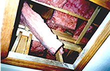
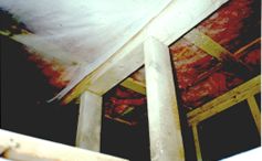
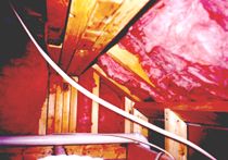
Following the infrared work, photographic and video records of snow, frost, and ice patterns were made to complement the thermography. This was followed by physical inspections of easily accessible areas such as attic and basement areas. The owners had photos taken throughout the previous winter to supplement the initial test phase data, and ongoing monitoring of modified and unmodified units enabled documentation during various levels of snow accumulation and at various temperatures. (Note: In projects where it isn’t possible to access attic spaces or when melt pattern analysis isn’t feasible, creating a negative pressure in the units with blower door test apparatus overcomes the stack effect in the building making all of the leaks inward. This allows them to be scanned from the inside. Pressurized fog analysis is also a useful tool in locating air- leakage sites). Finally, Phase I areas that could not be inspected without opening the building envelope were dismantled and the inspections were completed. Phase II non-destructive diagnostic information was collected with the same techniques as Phase I. Additional destructive testing was not required. Theoretical ConsiderationsThe process outlined above required two phases of testing and remediation work. In the first series of testing procedures (Phase I), only major conductive and air-leakage loss areas could be identified because the larger losses overwhelmed or "concealed" smaller ones. In the case of air leakage, large openings reduced the pressure differential across the barrier, and the smaller, more restricted openings had little or no flow. In conductive loss areas, large un-insulated sections of wall or roof concealed or reduced the apparent importance of relatively poor R-value areas. The initial (Phase I) testing gave an overall sense of the problem and determined that the primary causes of the ice formation were not failures in the insulation or ventilation systems in the cathedral roofs. It identified the areas requiring improvements and aided in prioritizing them. This procedure also provided a benchmark for comparative quality assurance procedures for the project. After the Phase I improvements had been completed, the infrared and melt patterns in Phase II testing provided much more concise information about smaller, concentrated, heat-loss sites. The pressure differential across the remaining small openings increased, allowing them to be easily detected. The second round of testing also gave the contractor making the improvements feedback about the initial round of work. Usually, this was done prior to closing access areas and replacing finishes. By incorporating a review step and fine-tuning into the planning, there was less pressure to address potentially low-payback repairs in the first phase, resulting in cost savings on several occasions. This also allowed everyone involved to assess the impact of the initial work, and to develop and try alternative techniques to overcome problems encountered in the first Phase. Creating a cooperative effort where everyone worked together to accomplish practical goals resulted in a much lower probability of failure. For all of these reasons, it was clearly important that at least two series of tests be performed. While this case study highlights the test methods, the construction details contributing to ice dam formation, the contractor’s approach to the work, the details of the repairs, and the resulting effects on ice dam formation and energy usage, it also addresses the importance of communicating the goals of the work to the contractor providing the solutions. In these buildings, many of the causes of these ice dams could have been prevented at a much lower cost during the original construction if there had been an understanding of the intended function of the individual components of the thermal envelope. Bridging the gap between building science and field practice is one of the crucial challenges of achieving successful results in both new construction and this type of remedial work. The diagnostician or designer must be able to convey what the problem is, how the building materials can combat the problem, and then support the installer by quality assuring the work during the process. "Seeing" evidence of the problems and successes through the use of photos, infrared scans, observing melt patterns, or with pressurized fog analysis, is the most effective communication tool available. In this project, once the contractor had seen the evidence from the diagnostic procedures and gained an understanding of the problems that he had to address, he developed a very effective strategy for the necessary improvements. He was also prepared to make independent decisions when new or unexpected problems were encountered. The tests clearly showed that the vast majority of the heat-loss problems contributing to ice dam formation were related to the integrity of the air barrier assemblies (Air barriers are equated here with sealed "sheathing" or "closure" materials). In the worst cases, there was nothing between the interior (warm) and exterior (cold) spaces but the friction-fit un-faced batts (typical insulation), and in many cases the batts had gypsum board on the warm side but were unsheathed or open on the exterior side. It is proven that air barriers are necessary to the performance of conventional batt insulation. Less frequently the batts were closed in (sheathed) on both sides, but in all cases there were penetrations and unsealed joints in the sheathed surfaces. In order to prioritize the theoretical requirements for insuring the continuity of air barriers and maximizing the thermal performance of the existing batt insulation, all of the thermal envelope conditions were referred to as one of three types:
The goal presented to the contractor for this project was to upgrade any conditions in types #1 and #2 above to type #3. In areas where the sheathing (air barrier) was missing, the surrounding air barriers were to be identified, and materials selected to provide an air-tight connection between the existing air barriers. The contractor’s choice of materials was usually dependant upon the difficulty of the access to the work space. Where possible and practical, foil-faced rigid foam sheets were used, not only to complete the missing air barriers, but to provide added R-value. Accessible air-leakage gaps in existing air barriers were also sealed. All existing ventilation provisions were maintained and locations with no insulation were upgraded to match the original specified levels (R=11 or 19 in walls, R = 30 in roof slopes, R = 30 in flat attic caps). These values met the minimum local code requirements at the time they were approved. There was clear visual evidence of air flow through penetrations and the “open on both sides” (Type #1 - no air barriers) conditions from mold and mildew and heavily concentrated melt areas. These were easily located. There was little obvious physical evidence for the single-sided (type #2 - one air barrier) condition. Not until Phase II, after the Type #1 problems had been repaired were the Type II problems visible except with infrared equipment. For this reason, a study was performed at one of the typical examples of this condition ? a bathroom knee wall. The temperatures on both sides of the wall and in the roof vents above this condition were monitored before and after installing a second air barrier on the exterior side of the wall. This test demonstrated that the wall performance was improved by reducing convection in the batts and reducing ex-filtration through penetrations; therefore, the amount of heat that was “lost” into the roof slopes and attic above the knee wall was reduced. Roof melt patterns clearly corroborated these findings. The test was intended to show the owners that roof surfaces can be warmed by seemingly unrelated sources in walls and ceilings well below the affected roof area1.
| |||||||||||||||||||||
 |
|||||||||||||||||||||||